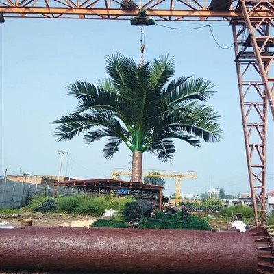
As a crucial component of smart city infrastructure, smart light poles integrate multiple functions, including lighting, surveillance, communications, and environmental monitoring. The rigor and technical nature of their production processes directly impact product reliability and performance. This article details the entire production process for smart light poles, from raw material preparation to finished product delivery, covering key steps and key technical points.
1. Raw Material Preparation and Inspection
The production of smart light poles begins with the selection and inspection of high-quality raw materials. Key materials include high-strength steel (such as Q235 or Q355), aluminum alloy (for some lightweight components), LED light source modules, sensor components, communication modules (such as 5G micro base station interfaces), and composite materials (such as explosion-proof glass or PC covers).
Primary raw materials undergo rigorous quality inspections before entering storage. These include testing the steel's mechanical properties (tensile strength and yield strength), evaluating the surface corrosion treatment (such as hot-dip galvanizing thickness), and testing the electrical performance and compatibility of electronic components. Unqualified materials are rejected to ensure reliability in subsequent processing.
II. Light Pole Main Structure Processing
1. Cutting and Forming
The steel is precisely cut according to the design drawings. Common processes include CNC plasma cutting and laser cutting to ensure cross-sectional flatness and dimensional accuracy. The pole body typically adopts a tapered or uniform diameter structure and is formed using a press brake or die stamping. Some complex curved surfaces require hydroforming.
2. Welding and Splicing
The main structure of the light pole is spliced using automated welding (such as MIG/MAG welding) or robotic welding. Welds must comply with national welding standards (such as GB/T 12467) and undergo non-destructive testing (such as ultrasonic testing or X-ray testing) to eliminate internal defects. After welding, straightening is required to ensure that the pole straightness error does not exceed 1/1000 of the design value.
3. Surface Treatment
To enhance corrosion resistance and aesthetics, the pole surface undergoes pre-treatment (degreasing, rust removal, and phosphating) before being hot-dip galvanized (zinc layer thickness ≥ 85μm) or electrostatically sprayed. The spray coating material is typically a weather-resistant polyester powder, and the color and coating thickness (≥ 100μm) must meet requirements for long-term outdoor use.
III. Functional Module Integration
1. Lighting System Installation
LED lamps are connected to the reserved connectors at the top or center of the pole using waterproof connectors. Circuit wiring utilizes flame-retardant cable and is isolated from the metal housing by rubber seals to ensure an IP65 or higher protection rating. An intelligent dimming module (such as DALI or ZigBee protocols) is integrated into the control box, enabling remote brightness adjustment and fault diagnosis.
2. Intelligent Sensors and Communication Equipment
Environmental monitoring sensors (such as PM2.5, temperature and humidity), cameras, and 5G micro base station antennas are secured to the middle or top of the pole using custom brackets. Cables are routed through internal wiring troughs to prevent external interference. The communication module must pass EMC (electromagnetic compatibility) testing to ensure there are no signal conflicts with the lighting system.
3. Power Supply and Control System
A waterproof distribution box is installed at the base of the light pole, housing a surge protector (SPD), a smart circuit breaker, and an edge computing unit, supporting both mains and solar power supply solutions. The control system utilizes PLC or LoRa/NB-IoT protocols to enable multi-device linkage, with data transmitted to a cloud platform for centralized management.
IV. Assembly and Commissioning
1. Overall Assembly
Each functional module is positioned and secured on the final assembly line. The light pole is connected to the base flange with high-strength bolts (torque values must meet design requirements), and verticality is calibrated using a spirit level (deviation ≤ 0.5°).
2. Functional Testing
The assembled smart light pole undergoes a full-load power-on test to verify lighting performance, sensor data acquisition accuracy, and communication stability. Weather resistance is tested by simulating extreme environments (such as high temperatures and rain) to ensure normal operation within a temperature range of -40°C to 85°C.
V. Quality Inspection and Shipping
Finished products must pass third-party certification for electrical safety (GB 7000 series standards), mechanical strength (wind pressure resistance ≥ 12), and intelligent functionality (response delay ≤ 1 second). Qualified products are affixed with a unique QR code, documenting the production batch and testing data. They are then packaged and shipped to the project site for installation.
Conclusion
The production process for smart light poles integrates materials science, machining, electronic engineering, and IoT technologies. The standardization and refinement of these processes are fundamental to ensuring the efficient operation of smart cities. In the future, with advances in new materials and intelligent control technologies, the production process for smart light poles will further develop towards higher integration and lower carbon emissions.